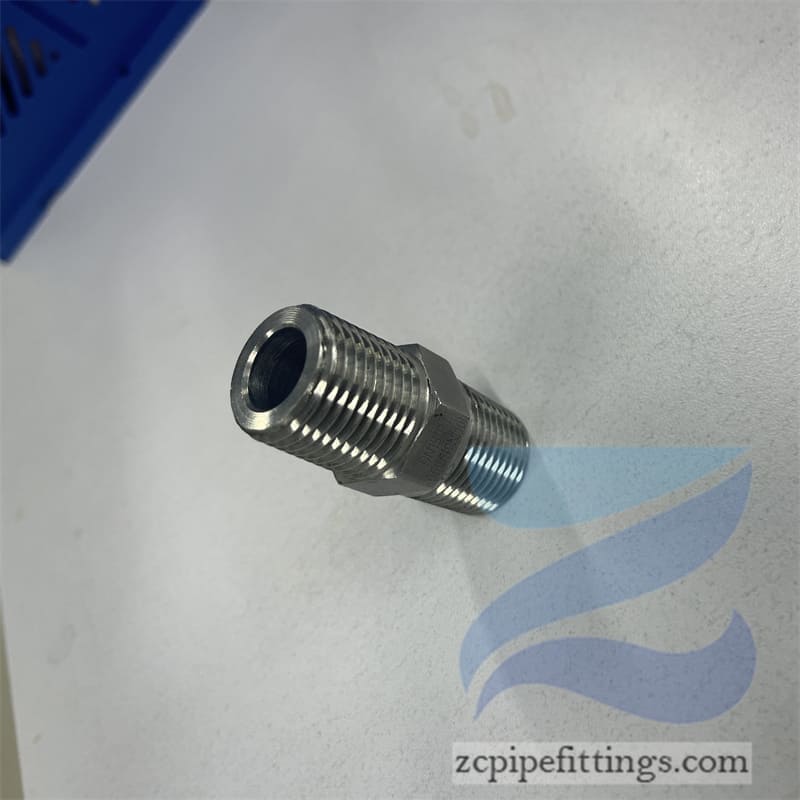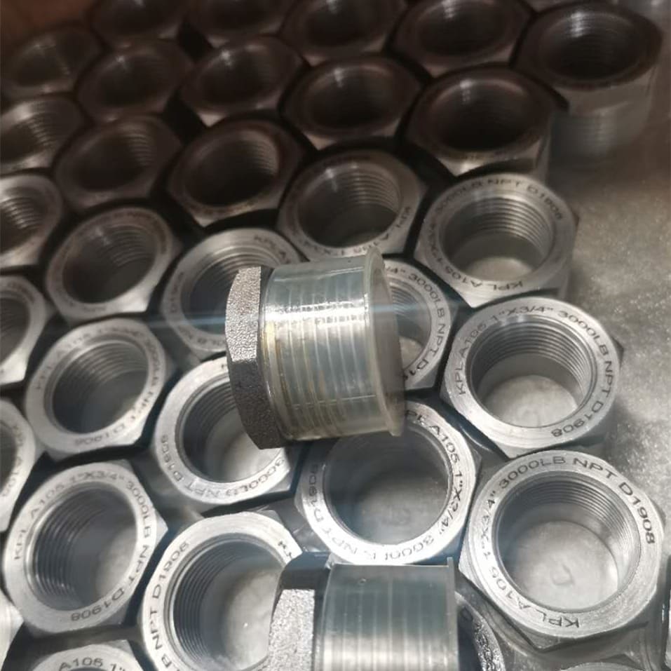
Alloy Steel A182 Swage Nipple Dimensions
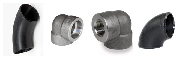
They are concentric and eccentric available, with various ends. The most common types are:
PBE nipple = Plain Both Ends
BBE nipple= Beveled Both Ends
TBE nipple= Treaded Both Ends
Production Description
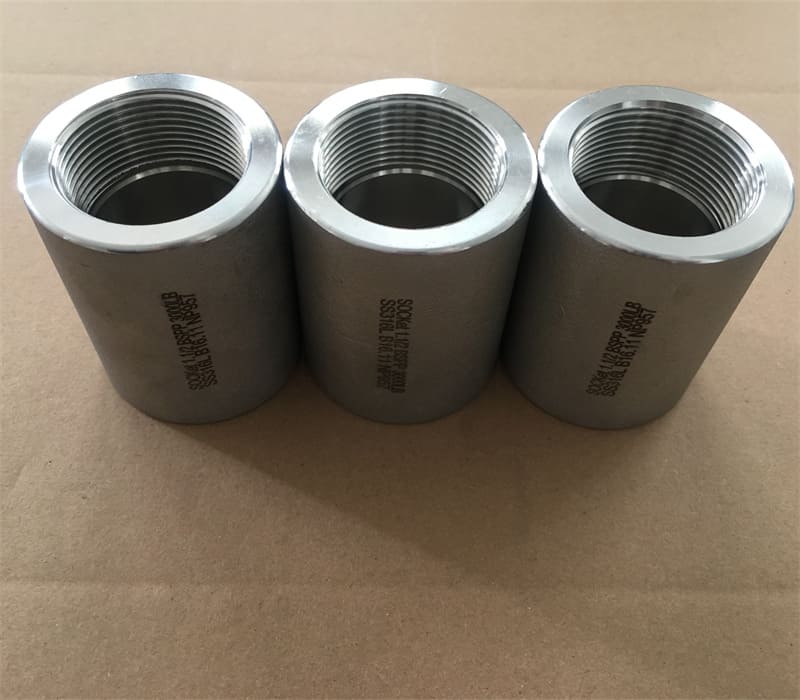
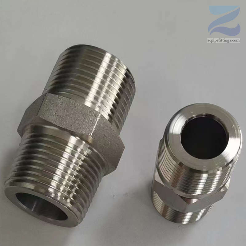
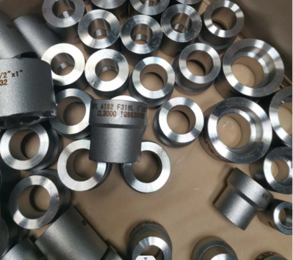
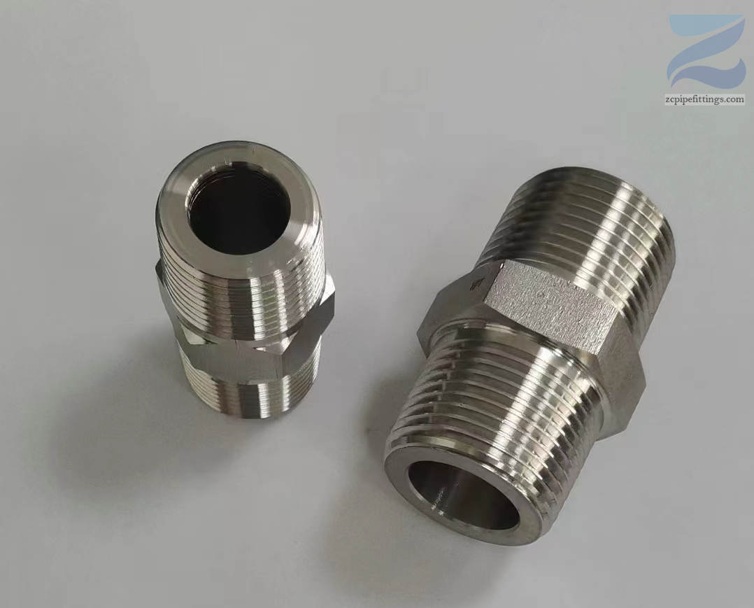
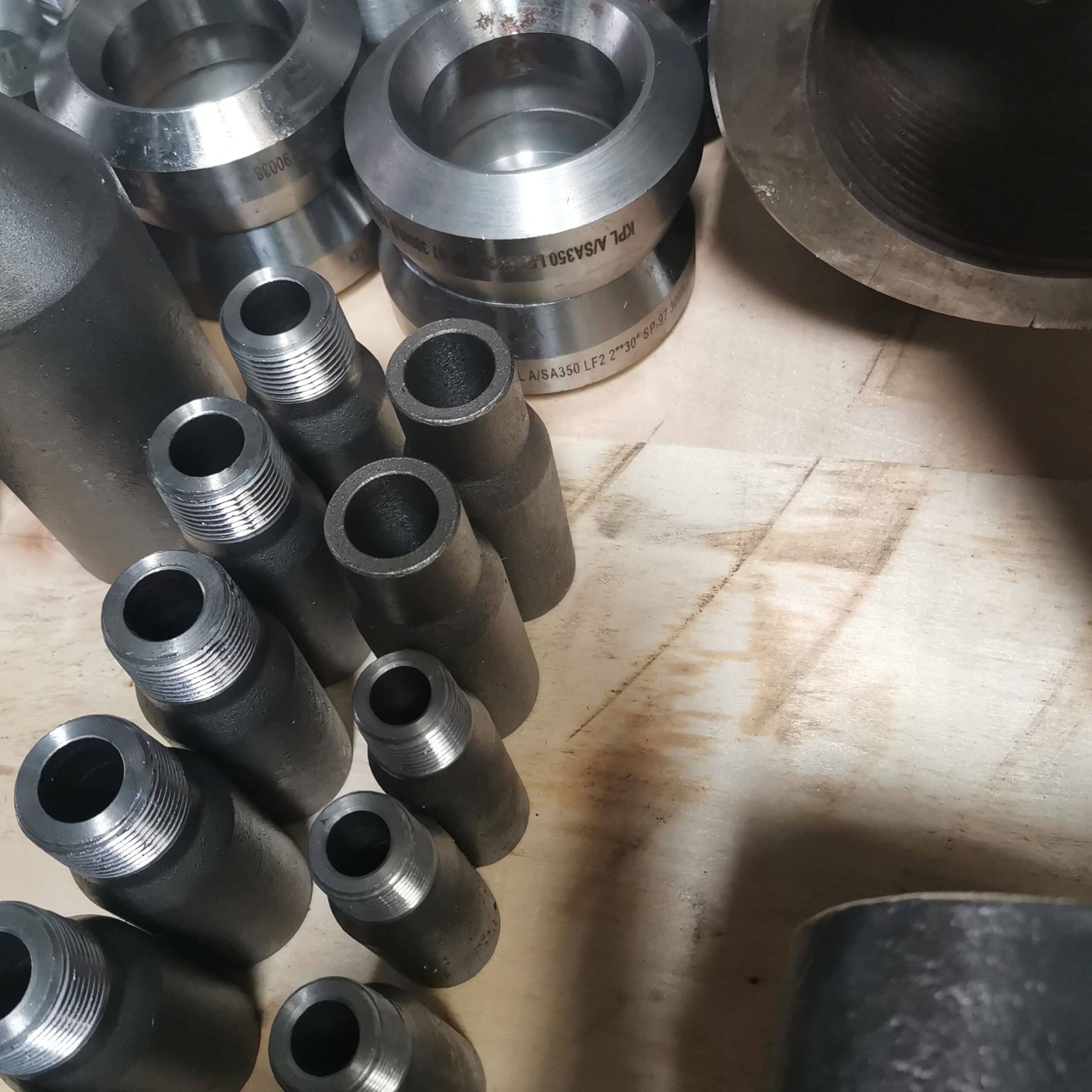
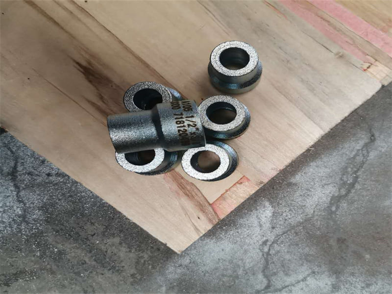
Alloy Steel A182 Swage Nipple Dimensions (also known as reducing nipple) is a forged pipe fitting. It is used to change the diameter of the pipe and connect two pipes of different sizes.
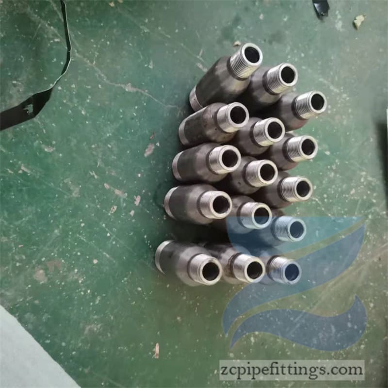
A pipe nipple is a length of straight pipe with male threads on both ends. It is one of the most popular category of pipe fittings. It is a connector or a coupling threaded on both ends. PBE Pipe nipples are used to allow plumbing to be connected to a water heater or other plumbing. They are used to fit straight end hose or pipe. A combination of pipe nipples are recommended for low-pressure discharge and suction service for various compatible liquids and not for compressible products like air, nitrogen or steam.
Shapes:
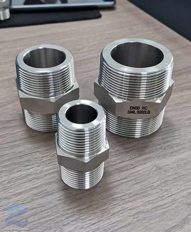
Concentric: Concentric swage nipple is mainly used for vertical pipeline.
Eccentric: eccentric swage nipple is mainly used in horizontal pipelines.
End Types:
PBE=Plain Both Ends
PLE=Plain Large End
PSE=Plain Small End
POE=Plain One End
TOE=Thread One End
TBE=Thread Both Ends
TLE=Thread Large End
TSE=Thread Small End
BBE=Bevel Both Ends
BLE=Bevel Large End
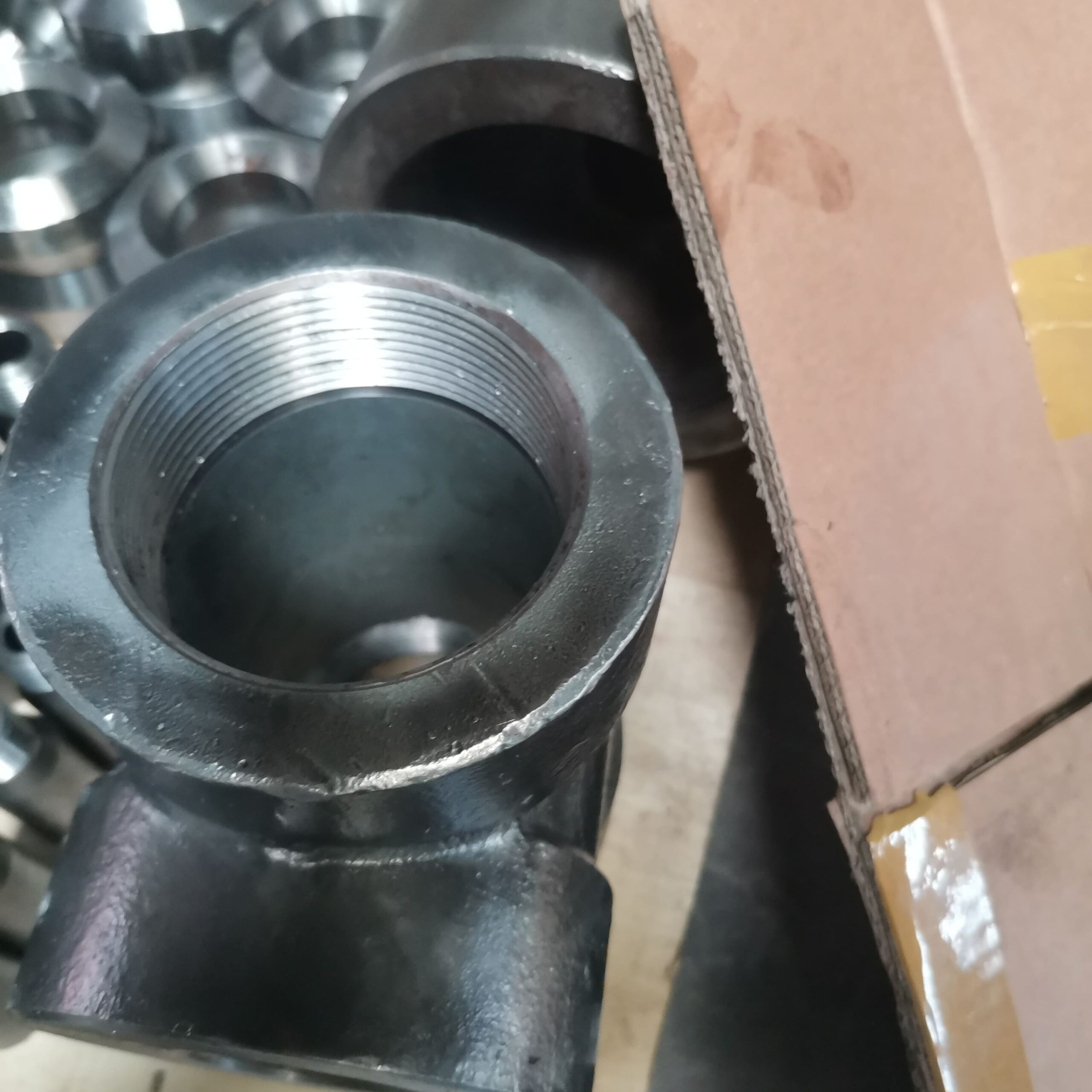
Product features
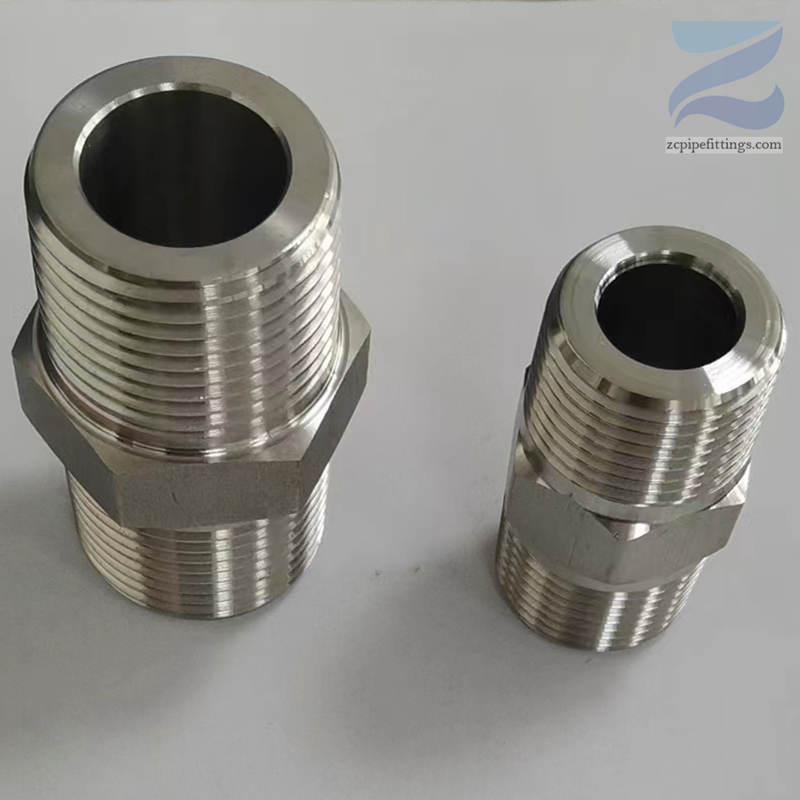
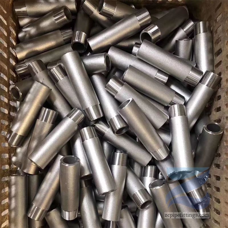
Swage nipples are often used in small diameter pipe systems, and are similar to butt weld reducers.
They are concentric and eccentric available, with various ends. The most common types are:
PBE nipple = Plain Both Ends
BBE nipple= Beveled Both Ends
TBE nipple= Treaded Both Ends
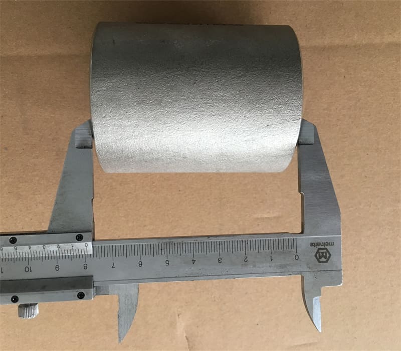
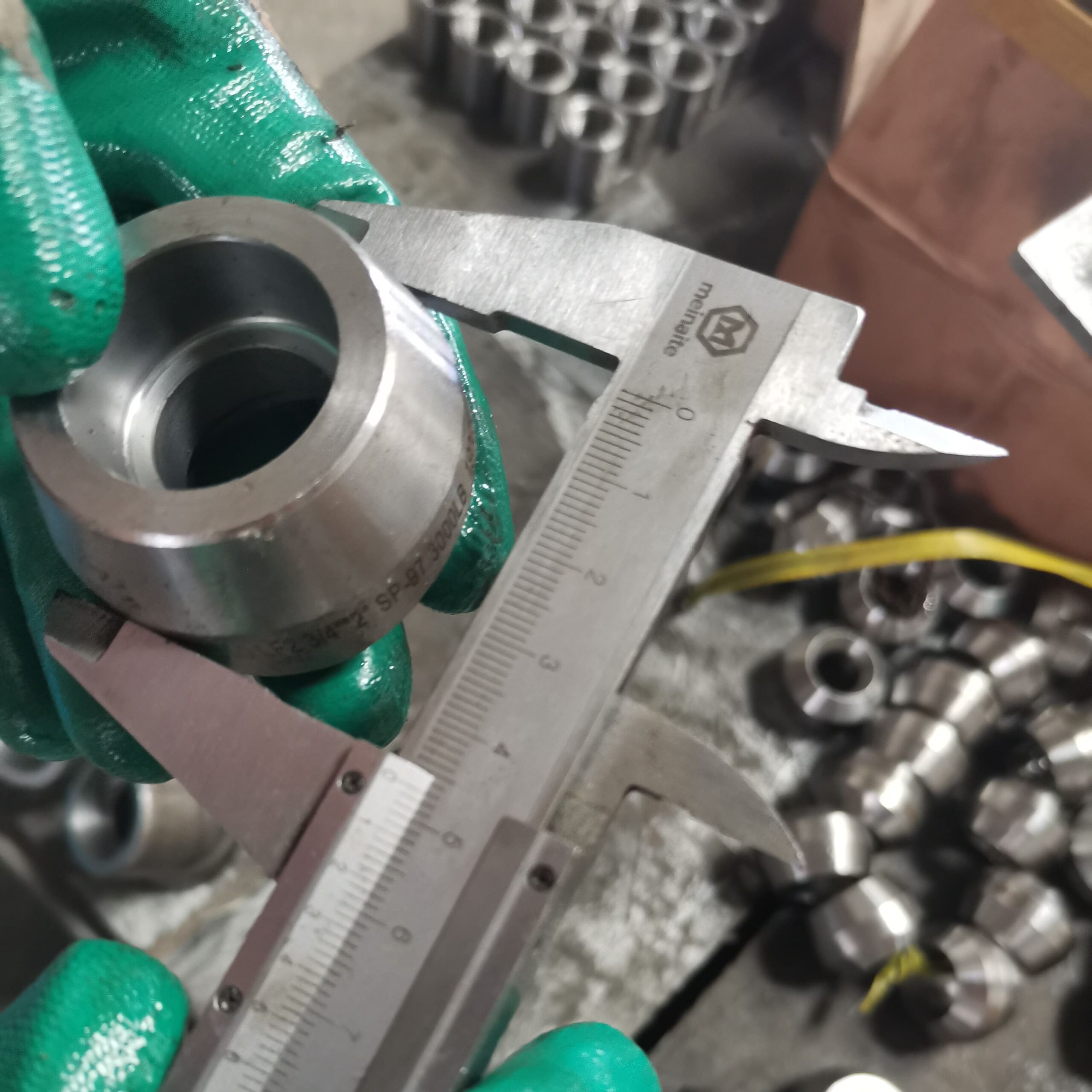
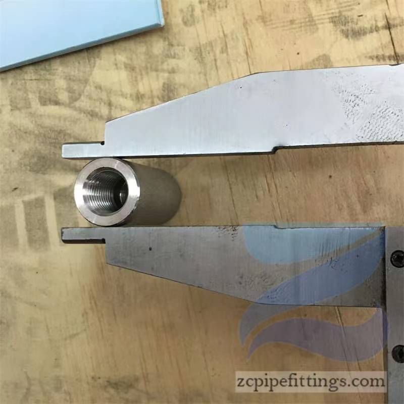
Specificaton of Alloy Steel A182 Swage Nipple Dimensions
| Size Range | 1/8″ – 4″ / DN6 – DN100 |
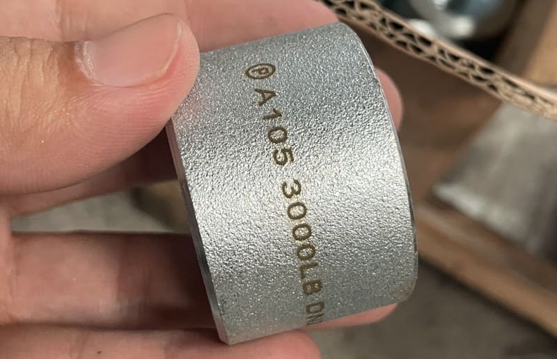
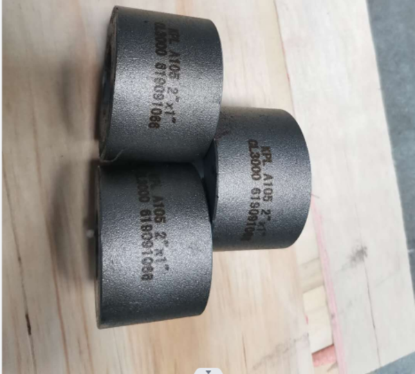
| Pressure Rating | Class 2000lbs, 3000lbs, 6000lbs |
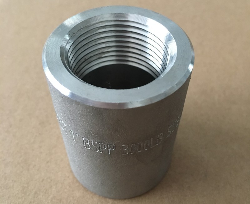
| Thread Type | NPT, PT, BSPP, BSPT, PF |
| Standard | ASME B16.11, BS3799, EN 10241, MSS SP-83, MSS SP-97 |
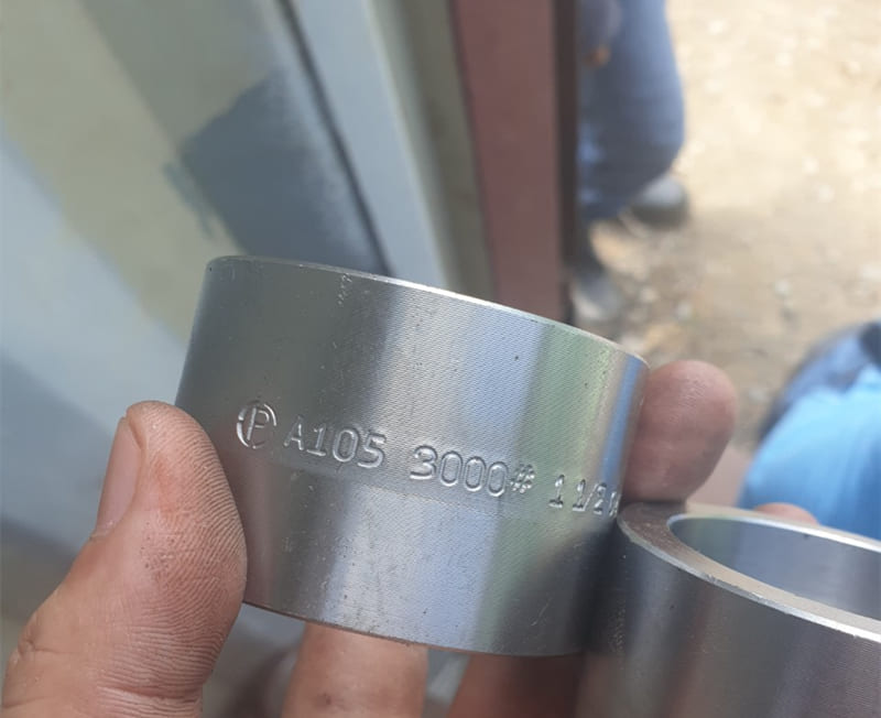
| Carbon Steel | ASTM A105 / A105N, ASTM A350 LF2/LF3, ASTM A694 F42 / 46 / 56 / 60 / 65, P235GH, P265GH, P280GH, P355GH |
| Alloy Steel | ASTM A182 F11 / 12 / 5 / 9 / 91 / 92 / 22 |
| Stainless Steel | ASTM A182 F304/304L/304H, 316/316L, 321, 310S, 317, 347, 904L,1.4404, 1.4437. |
| Duplex Stainless Steel | ASTM A182 F51, F53, F44 |
Swage Nipple Weight Chart in kg
ASTM A182 F5 is a forging material specification for F5 grade alloy steel and is used for manufacturing bare forgings or forged and machined products for applications involving high temperature service.
It has a fairly high electrical conductivity among wrought alloy steels in the same category. In addition, it has a moderately high base cost and a moderately high embodied energy.
Chemical Composition
| Grade Symbol | Alloy | Elements | Composition % |
|---|---|---|---|
| F5 | 4% to 6% Chromium | Carbon | 0.15 max |
| Manganese | 0.30 – 0.60 | ||
| Phosphorus | 0.030 max | ||
| Sulfur | 0.030 max | ||
| Silicon | 0.50 max | ||
| Nickel | 0.50 max | ||
| Chromium | 4.0 – 6.0 | ||
| Molybdenum | 0.44 – 0.65 |
Mechanical Properties
| Property | Value |
|---|---|
| Tensile Strength, min, ksi [MPa] | 70 [485] |
| Yield Strength, min, ksi [MPa] | 40 [275] |
| Elongation in 2 in. [50mm] or 4D, min, % | 20 |
| Reduction or Area, min, % | 35 |
| Brinell Hardness Number, HBW | 143-217 |
Application:
- Petroleum
- Pulp/paper
- Refining
- Textile
- Waste treatment, Marine
- Utilities/power generation
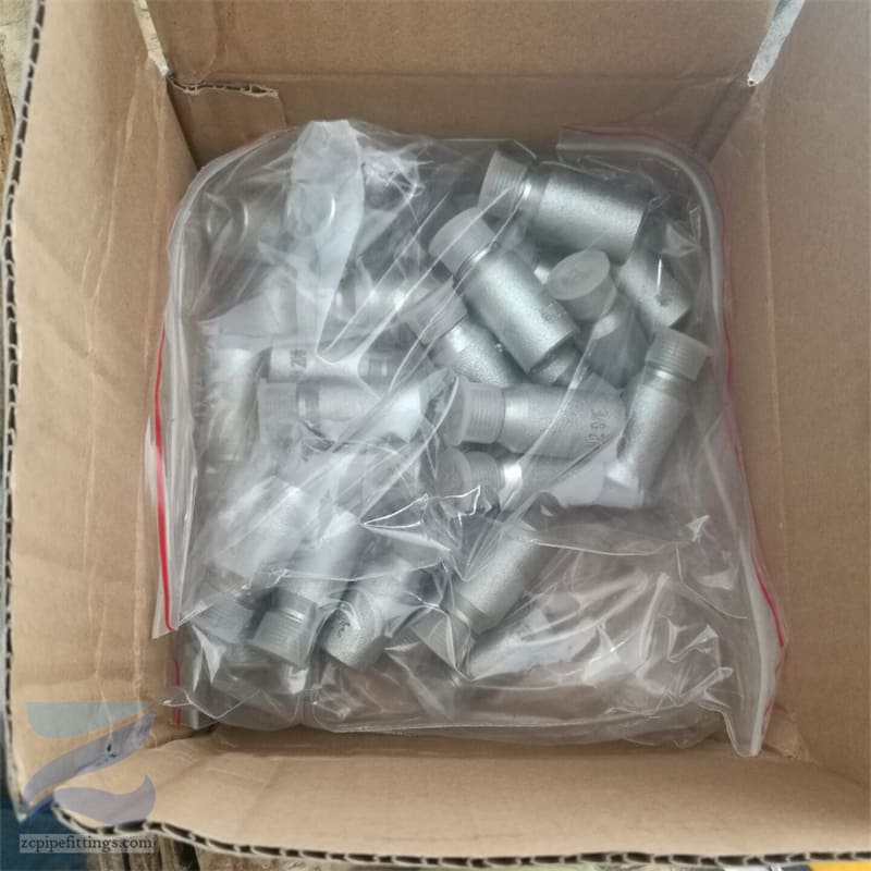
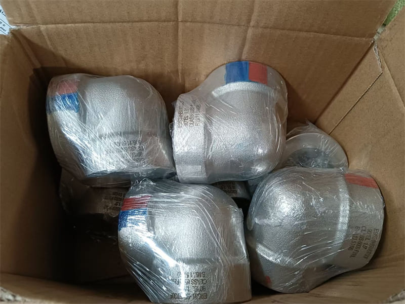
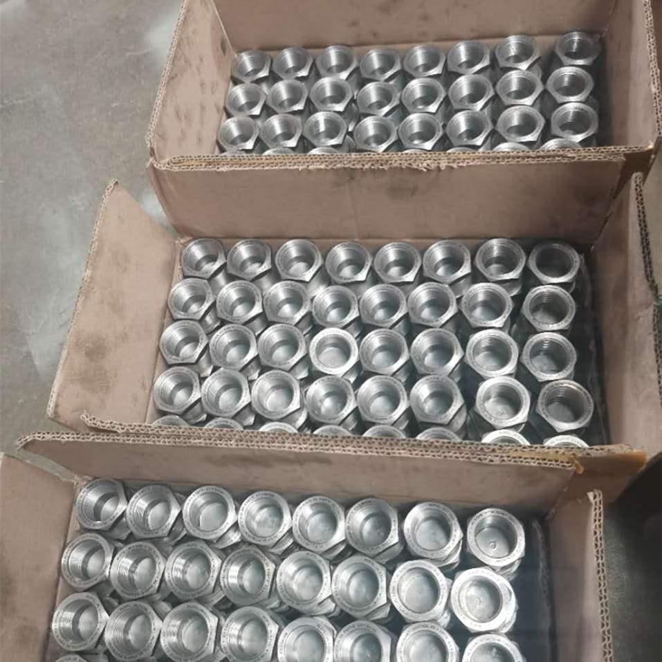
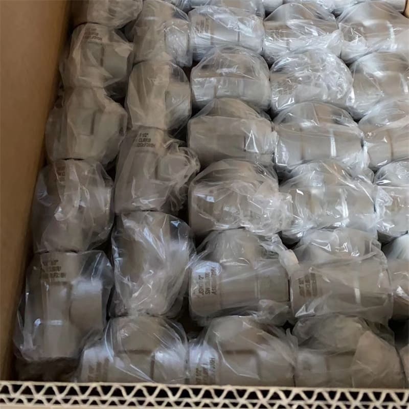
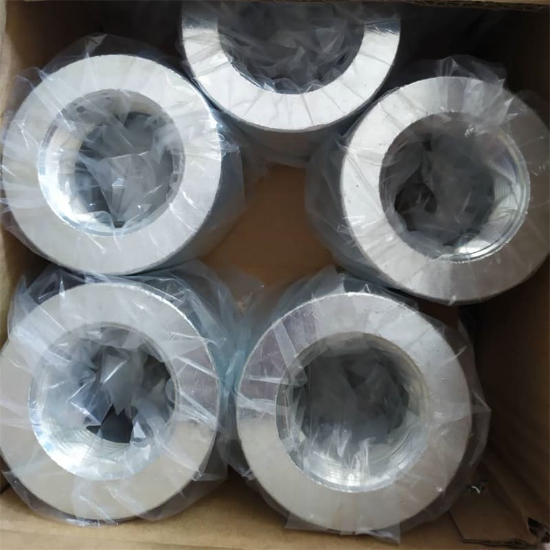
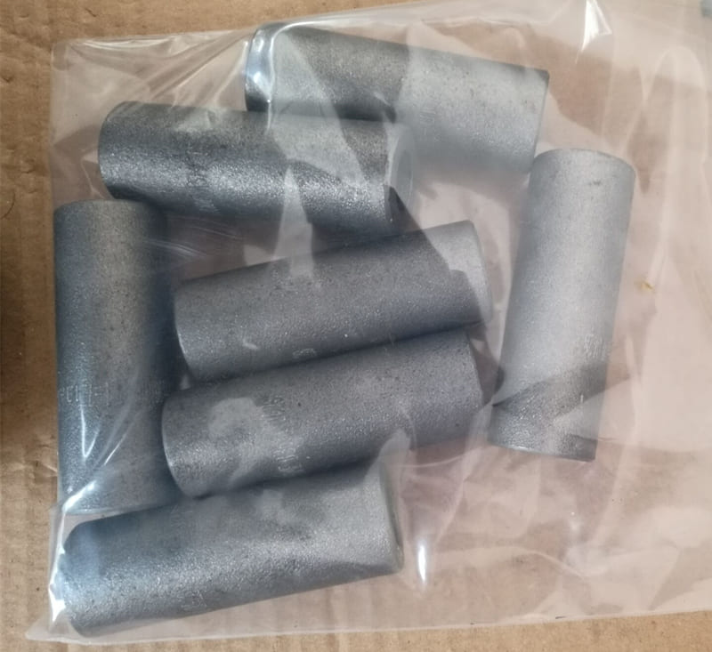
Packing Details